![]()
![]()
Top > Releases ・ Announcements > Press Releases > Status of TEPCO's Nuclear Power Stations after theTohoku-Chihou-Taiheiyou-Oki Earthquake > 2013 > Status of TEPCO's Nuclear Power Stations after the Tohoku-Chihou-Taiheiyou-Oki Earthquake (Daily Report as of 3:00 PM on September 25)
Due to the Tohoku-Chihou-Taiheiyou-Oki Earthquake which occurred on March 11, 2011, TEPCO's facilities including our nuclear power stations have been severely damaged. We deeply apologize for the anxiety and inconvenience caused.
With regard to the accident at Fukushima Daiichi Nuclear Power Station, on April 17, 2011, we have compiled the roadmap towards restoration from the accident and on July 19 we accomplished the Step1 target "Radiation dose is in steady decline". Then on December 16 we confirmed the accomplishment of the Step 2 target "Release of radioactive materials is under control and radiation doses are being significantly held down".
In addition, on December 21, 2011, we have compiled the "Mid-to-long-Term Roadmap toward the Decommissioning of Fukushima Daiichi Nuclear Power Units 1-4, TEPCO".
In addition to the maintenance of the plant's stable condition, we will implement Mid-to-Long Term countermeasures towards the decommissioning of Fukushima Daiichi Nuclear Power Units 1-4 to enable evacuees to return to their homes as soon as possible and reduce the anxiety of the people in Fukushima and the whole nation as soon as possible.
Below is the status of TEPCO's Fukushima Daiichi Nuclear Power Station.
*The updates are underlined.
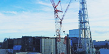
[Fukushima Daiichi Nuclear Power Station]
Unit 1 to 4: Abolishment (April 19, 2012)
Unit 5 to 6: Outage due to regular inspections before the earthquake
-Contaminated water transfer from the underground reservoirs was all completed as of July 1. However, we are continuing to take measures to prevent the expansion of contaminated water, and to conduct sampling activities.
<Measures to prevent the expansion of contaminated water>
·Since the decreases of all-β radioactivity densities in the leakage detection holes (at the northeast side of the underground reservoir No.1, the northeast side of the underground reservoir No.2, and the southwest side of the underground reservoir No.3) have been slow, operations to dilute the underground reservoirs No.1-No.3 by transferring filtered water or desalination-system (RO) treated water (the all-β radioactivity density: approx. 1x101Bq/cm3) into these reservoirs have been conducted as appropriate.
<Recent dilution operations>
·Underground reservoir No.1 (since June 19): On August 3, approx. 60m3 of filtered water was injected.
·Underground reservoir No.2 (since June 27): On August 1, approx. 60m3 of filtered water was injected.
·Underground reservoir No.3 (since July 24): On August 12, approx. 107m3 of water in the drain hole (northeast) of this underground reservoir was injected.
On September 24, leaked water in the leakage detection holes at the underground reservoirs No.1-No.3 was transferred to the temporary aboveground tank, and leaked water in the drain holes at the underground reservoirs No.1 and No.2 was transferred into these underground reservoirs.
<Sampling>
On September 24, sampling was performed at the drain holes of the underground reservoirs No.1-No.7 (14 locations), the leakage detection holes of the underground reservoirs No.1-No.4 and No.6 (samples could not be collected at 2 of 10 locations), the observation holes of the underground reservoirs (22 locations), the underground water bypass survey holes a-c (samples could not be collected at 1 of 3 locations), the groundwater bypass pump wells Nos. 1-4, and the seaside observation holes (1)-(4). No significant change was found in the analysis results in comparison to the analysis results on the samples collected the previous time (underground water bypass survey holes a-c (samples could not be collected at 1 of 3 locations), groundwater bypass pump wells Nos. 1-4, and the seaside observation holes (1)-(4): samples collected on September 17; others: samples collected on September 23).
In addition, no significant change was found in the results of analyses performed for tritium of the water samples collected over the period from September 16 to September 17 at underground water bypass survey holes a-c (samples could not be collected at 1 of 3 locations), groundwater bypass pump wells Nos. 1-4, and the seaside observation holes (1)-(8) in comparison to the analysis results of the previous time (seaside observation holes (5)-(8): samples collected on September 9; others: samples collected on September 10).
The all-β values of the leakage detection holes (on the southwest side) at underground reservoir No. 3 changed to increase again following the recommencement of construction work to counter uplift in the underground reservoir, and the countermeasure construction work for preventing uplift in the underground reservoir in question is to continue until the end of this month, so we believe that a change in density in the detection hole in question will be found after this.
-On August 19, puddles were found inside a dike around the H4 area tanks in the power station and outside of a drain valve of the dike.
We found water spread at the bottom level of tanks near Tank No.5 in the Group I in the H4 area. Therefore, we checked the water level of this tank, and found out that the water level has fallen by approx. 3m than the normal level (the amount of water: approx. 300m3). We started collecting the water remaining inside the dike and already collected some of the water. However, since it seemed that the water has flowed out of the dike through the drain valve, we are collecting soil in the surrounding area and continuing to conduct an investigation to find out the range reached by the water. Later, we found streaky traces of flows on the wall surface of a drainage channel located east of the H4 area tanks. The maximum surface dose equivalent rate measured at this location was 6.0mSv/h (β+γ rays (70μm dose equivalent rate)). As this information indicates the possibility that contaminated earth and sand, etc. may have flowed into the drainage channel, we are planning to conduct a detailed investigation and evaluation concerning these traces.
On August 22, transfer of water stored in Tank No.5 in Group I in the H4 area and water collected in a temporary tank (water accumulated inside the dike) into Tank No.10 in Group B in the H4 area was completed.
On August 22, we conducted full inspections (appearance inspections and dose measurement) on the flanged tanks in the other areas, which are of the same type as the tank from which water has leaked. Neither leak nor puddle was found by the appearance inspections on the tanks and the drain valves. However, 2 locations locally showing high dose rates were found around the H3 area tanks. The surfaces of these locations were dry, and we confirmed that there has been no water having flowed into the inside of the dike or the outside of the dike. We also confirmed that the water levels of these tanks remain unchanged after they received water. Additionally, we conducted soundness inspections (visual appearance inspections and water level confirmation) on the flanged tanks that are in use for storage of accumulated water from Units 5 and 6. The inspections were completed on August 26 and showed no abnormality.
During our inspection of Tank No.5 in Group I in the H4 area from which water has leaked, we found out the following:
·3 tanks including this tank (Tank No.5 in Group I, Tank No.10 in Group I, and Tank No.3 in Group II in the H4 area) were initially installed in the H1 area.
·Ground subsidence occurred in the H1 area at the foundations on which these tanks had been placed, and these tanks were planned to be installed in the H2 area, but actually, have been placed in the H4 area despite our plan.
Although it is still unclear whether there is a causal relationship between the water leaking of Tank No.5 and the tank's having experienced ground subsidence occurred in the H1 area at the foundation on which it had been placed, we conducted water transfer from inside Tank No.3 in Group II in the H4 area to Tank No.10 in Group B in the H4 area to reduce the risk of leakage.
<The latest transfer operations>
·At 3:57 PM on August 25, transfer from Tank No. 10 in Group I in the H4 area to Tank No. 10 in Group B in the H4 area was started. At 2:07 AM on August 27, the transfer was completed.
·At 10:30 AM on August 29, transfer from Tank No. 3 in Group II in the H4 area to Tank No. 10 in Group B in the H4 area was started. At 2:07. At 11:03 AM on September 2 water transfer was suspended due to the implementation of rainfall countermeasures.
During a patrol on August 31, we found 4 locations showing high dose equivalent rates (γ and β rays (70μm dose equivalent rate)). We consider that there has been no leakage to the outside of the dike because the water levels of all of the relevant tanks have not decreased and also because the drainage valves have been closed.
One of the 4 locations, the connecting pipe section between Tank No.5 and Tank No.6 in Group IV in the H5 area has the heat insulation material placed in the upper part of the pipe, and one drop of water fell to the floor surface when this heat insulation material was pressed. The dose equivalent rate at a location on the floor surface to which the water fell was measured and confirmed to be approx. 230mSv/h. Although water then stopped dropping from the connecting pipe, a discolored part (in a dry condition) of approx. 20cmx20cm was found on the floor surface under the pipe section. Then, we checked the status of water dropping from the connecting pipe between Tank No.5 and Tank No.6 in Group IV in the H5 area with the heat insulation material having been pulled out. Then, we found out that a flange part connecting an isolation valve on the Tank No.5 side (there are 2 isolation valves connecting these tanks and connecting pipe) and the connecting pipe was dripping one drop per approx. 90 seconds. In response, on the same day, we wrapped the adsorption mat around this flange part and covered it with plastic-sheet protection, while placing a drain receiving pan under the flange part on the floor. Both of the 2 isolation valves on the respective Tanks No.5 and No.6 sides of this connecting pipe were found to have been closed. On September 1, we tightened up 12 flange bolts at this flange part, and we confirmed that no water leakage was occurring. For the confirmation purpose, the water levels of Tank No.5 and Tank No.6, in Group IV in the H5 area, were measured and found unchanged.
<Results of the latest patrol>
During a patrol on September 24, no location showed a high dose equivalent rate (β and γ rays (70μm dose equivalent rate)). Locations near the dike floor continued to show low dose equivalent rates since rainwater accumulated inside the dike (approx. 3 to 4 cm deep) worked as a shield. Additionally, we conducted a visual inspection, and all of the tanks were found without any abnormality such as leakage (except for within accumulated water inside the dike where leaks could not be confirmed). No abnormalities were confirmed in the water level by means of thermography (results of analysis of images taken on September 23).
As a result of the full inspections (appearance inspections and dose measurement) conducted on August 22 on the tanks in the areas other than the H4 area, we found tanks (Tank No.4 in Group B and Tank No.10 in Group A, both in the H3 area) each having a part locally showing a high dose rate. Although no water dropping was found on the outside of these tanks, we transferred water inside the tanks to an RO waste liquid supply tank since August 29 and completed by September 18. Also, the transfer of residual water in Tank No. 10 in Group A in the H3 area to Tank No. 5 in Group B in the H3 area has been completed.
Following the leakage from a tank this time, we sampled water at the point near the south water outlet (T-2), at the junction of the drainage channels B and C near the H4 area (C-1), at the point immediately short of the junction with the drainage channel C (B-3), at the point near Fureai Intersection in the drainage channel B (B-0-1), at the point near the main gate in the drainage channel C (C-0), and at the drainage channel C OP. 35m exit (C-2) (on September 24), and conducted nuclide analysis on the water. The analysis results showed no remarkable change from the previous day (sample collected on September 23).
We conducted analysis for all-β and tritium on water in observation holes installed near the H4 area tanks.
The analysis results for all-β in samples collected on September 24 from an observation hole (E-5) around the H4 area, which was newly analyzed this time, found a value of 100Bq/L. No significant change was found in the analysis results for tritium in samples collected on September 23 from observation holes (E-1, E-2, E-3, E-4) around the H4 area in comparison with the analysis results for samples collected on September 22.
In addition, there was no significant change in the analysis results for all-β in samples collected on September 24 at observation holes around the H4 area (E-1, E-2, E-3, E-4) in comparison to the analysis results for samples collected on September 23.
·We installed observation holes east of the Unit 1-4 Turbine Buildings, and have been conducting sampling and analysis of groundwater from the observation holes. On June 19, we announced that tritium and strontium were detected at high densities in the observation hole located between Units 1 and 2. Therefore, we have been conducting intensified monitoring and have been pumping up groundwater at the well point and the water collection point (south) on the east of Unit 1 and Unit 2 Turbine Buildings.
<The latest groundwater transfer operation>
At 3:50 PM on August 31, the water transfer to the Unit 2 vertical shaft C from the well points and the water collection pit (south) was suspended, and the water transfer to the Unit 2 Turbine Building was started at 3:55 PM on August 31.
So that water in the Unit 2 vertical shaft B (water collected due to the closure of the trench) could be transferred to Unit 2 Turbine Building during the daytime from September 3, groundwater transfer from the well points and the water collection pit (south) was conducted while the transfer destination was sequentially changed. The work of closing the trench was almost completed, and transfer of groundwater in the well points and the water collection pit (south) to Unit 2 Turbine Building has been underway.
<Sampling>
-We conducted a purification test of wells (sub-drain pits) located next to the Units 1-4 buildings at Fukushima Daiichi NPS, and detected radioactive materials in water accumulated in the pits. One possible cause of the entrance of radioactive materials there is fallout. In order to find out the influence of fallout, we have been installing new observation wells around the Units 1-4 buildings.
*At 8:40AM on September 5, a TEPCO employee confirmed that the jib (crane arm) of a 600-ton crawler crane, which was being used for work removing debris from the upper part of the Unit 3 reactor building, was inclining, and later, at 11:43AM, that the component connected to the main mast was damaged.
Subsequently, to put the crane in a safer state, another crane was used from 8:20PM until 11:55PM on September 5 to hoist the hanging hook on the crane in question so as to rotate it and set the hanging hook and jib tip, which were inclining, on the ground west of the Unit 3 waste treatment building.
On September 10, work was performed to turn over the jib and main mast in order to inspect the crane in question.
From the results of the investigation into the cause, it was inferred that the coupling (threaded coupling) of a hydraulic hose for the drum lock (operated hydraulically) on the winch, which winds a wire cable rolling the crane tip jib mast, had loosened and the drum lock had been released, which resulted in slack in the wire cable and the tip jib mast gradually inclining and because of this, an unexpected load had been placed on the main mast and a crack resulted in the base of the upper part of the main mast. As a recurrence prevention measure, the component was replaced with a new part for the threaded coupling in question on the crane, and before starting and concluding work on days when this crane and another 600-ton crawler crane are operated, confirmation will be performed to make sure that there is no slack in the threaded coupling and that the lock is fastened on the drum in question. Also, an indicator light will be installed so that remote confirmation is possible to check that the lock is fastened on the drum in question.
*At around 3:20 PM on September 12, a TEPCO employee found water leaking from the accumulated water treatment system (vehicle-mount type) for Units 5 and 6. Accordingly, the accumulated water treatment system was immediately stopped, and it was confirmed that the water leak stopped. We performed a detailed investigation as to the range over which the leaked water has spread, and found traces of water leakage sized approximately 2mx6m in the trailer on which the accumulated water treatment system has been mounted. Water having leaked from inside to outside the trailer was found over a range of approximately 3mx3mx1mm. The amount of the leaked water was estimated to be about 0.065m3 based on the leakage time, the flow rate, etc. Given that there is no watercourse such as a drainage ditch around the system, we consider that the water having thus leaked has not flowed into the sea. Further, we sampled and analyzed the leaked water, and the water showed almost the same values as water used for sprinkling at the site*.
<Results of leaked water samples>
Cesium-134: Below the detection limit value (detection limit value: 1.6x10⁻³Bq/cm3)
Cesium-137: 4.2x10⁻³Bq/cm3
All-β: Below the detection limit value (detection limit value: 1.4x10⁻²Bq/cm3)
*Radioactivity density of water which could be used as sprinkling water: The sum of cesium-134 and cesium-137 should meet 1x10⁻²Bq/cm3.
The results of the investigation into the cause showed that because one of the valves for sending water from the RO system to the water retention tank for the on-site water sprinkler was in the "closed" position, pressure in the RO system outlet pipe rose and the safety valve was activated. The safety valve drainage flowed into the flushing cistern as it was discharged, but the flushing cistern could not receive it all, and the water overflowed. As to the factor causing the one valve for sending water to the water retention tank for the on-site water sprinkler to be in the "closed" position, we inferred that during work near the valve in question, a worker may have inadvertently come into contact with the handle of the valve and closed it. Also, because this valve was normally open, when sending water from the RO treatment system to the retention tank for the on-site water sprinkler, a worker may have assumed that the valve was open and not verified the position of the valve. As recurrence prevention measures, we will remove the handle from the valve so that it is not possible to easily operate it, attach a warning label to the valve, change the discharge location of the safety valve from the flushing cistern to the RO system intake chamber to avoid any overflow from the flushing cistern (by having it discharged into the intake chamber, any discharged water will circulate within the RO system), and review valves which are not normally operated in the RO system operating procedures so that confirmation is performed to verify the valve "open" or "closed" during system configuration of the RO system.
*At around 9:20AM on September 25, when a contractor worker was patrolling the F area tanks (north side of Unit 6) *, he discovered bleeding on the insulation material of a connecting pipe between the H1 and H2 tanks. Also, he confirmed traces where drops had fallen on a steel plate liner, which was installed under the insulation material. Subsequently, when the insulation material on the connecting pipe (polyethylene pipe) was removed to perform confirmation, it was found that it was not a leakage. Based on this, we determined that the bleeding in question was either rainwater or dew condensation water.
*Tanks holding retained water for the Unit 5 and 6 buildings.
*At around 11:17AM on September 25, a TEPCO employee found that water was dripping from an air-conditioning duct in the upper part of the stairwell on the northwest side of the 4th floor of the Unit 5 reactor building. Subsequently, when the actual field conditions were investigated, we found that there was dew condensation water on the air-conditioning drainage pipe, which is above the air-conditioning duct in question.
*On September 25, dust samples were collected in the upper part of the Unit 3 reactor building.
*On September 25, samples were collected from the charcoal filter and particle filter of the Unit 3 primary containment vessel gas control system.
![]()
In Order to view the PDF documents, you will need a software product called Adobe® Acrobat® Reader installed on your computer. You can download this software product for free from Adobe's Web site by clicking the left button:
![]()
![]()
© Tokyo Electric Power Company Holdings, Inc.